
Berbagi Informasi Teknik Elektro dan Elektronika
Saturday, November 16, 2013
Artikel tentang Free Energy Technology
Sobat blogger yang terhormat, mungkin beberapa artikel ini dapat dijadikan referensi untuk mengaplikasikan teknologi free energy :
Water Level Control - Cheap Semi Automatic
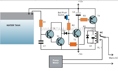
Skema Water Level Control (Semi Automatic)
Komponen :
R1 = 1K,
R2 = 470K,
R3 = 10K
R4 = 100K
T1, T2, T3 = BC547,
T4 = BC557
R2 = 470K,
R3 = 10K
R4 = 100K
T1, T2, T3 = BC547,
T4 = BC557
C1 = 0.22uF
C2 = 10uF/25V
C3 = 100uF/25V
D1,D2 = 1N4148,
Relay = 12 volts/SPDT
Push Button = Bell push type
C2 = 10uF/25V
C3 = 100uF/25V
D1,D2 = 1N4148,
Relay = 12 volts/SPDT
Push Button = Bell push type
Rangkaian yang disajikan untuk memantau level air naik di dalam tangki dan secara otomatis mematikan motor pompa setelah air mencapai level tertinggi.
Rangkaian ini sangat sederhana dan dapat dipahami dengan uraian sebagai berikut :Rangkaian ini terdiri dari transistor dan beberapa komponen pasif lainnya .Transistor T3 dan T4 bersama dengan bagian-bagian yang terkait membentuk sirkuit latch sederhana .Ketika push button ditekan sesaat , T2 mendapat bias maju dan memberikan yang diperlukan biasing untuk T4 yang juga langsung bekerja.Ketika melakukan T4 , yang mengaktifkan relay dan motor pompa diaktifkan ON .Sebuah umpan balik tegangan dari kolektor T4 mencapai dasar T3 melalui R4 memastikan bahwa T3 tetap terkunci dan dalam modus melakukan bahkan setelah tombol dilepaskan .Setelah air mencapai tingkat ambang tangki terjadi kontak dengan sepasang terminal diposisikan pada ketinggian yang diinginkan di dalam tangki .Air menghubungkan dua terminal dan tegangan kebocoran mulai mengalir melalui mereka yang menjadi cukup untuk memicu pasangan Darlington terdiri dari T1 dan T2 T1/T2 melakukan dan segera alasan sinyal umpan balik pada dasar T3 .T3 dihambat dari biasi tegangan dan latch sehingga relay OFF.Rangkaian tetap dalam posisi ini sampai air di dalam tangki masuk di bawah terminal dan tombol push di ON lagi.
Over Head Tank Water Level Indicator cum Controller Circuit
The circuit provided in this article performs a dual function of both,
as an over head tank water level indicator as well as a controller. The
indications of the rising water are provided by five LEDs, which light
up sequentially in response to the rising water level inside the tank.

As soon as the water reaches the uppermost level of the tank, the last sensor positioned at the relevant point triggers a relay which in turn switches the pump motor for initiating the required water evacuating action.
The circuit is as simple as it could be. Use of just one IC makes the entire configuration very easy to build, install and maintain.
The fact that impure water which happens to be the tap water that we receive in our homes offers a relatively low resistance to electricity has been effectively exploited for implementing the intended purpose.
Here a single CMOS IC 4049 has been employed for the necessary sensing and executing the control function.
Another interesting associated fact that’s associated with CMOS ICs has helped in making the present concept very easy to implement.
It is the high input resistance and sensitivity of the CMOS gates which actually makes the functioning completely straightforward and hassle free.
As shown in the figure, we see that the six NOT gates inside the IC 4049 are arranged in line with their inputs directly introduced inside the tank for the required sensing of the water levels.
The ground or the negative terminal of the power supply is introduced right at the bottom of the tank, so that it becomes the first terminal to come in contact with water inside the tank.
It also means that the preceding sensors placed inside the tank, or rather the inputs of the NOT gates sequentially come in contact or bridges themselves with the negative potential as the water gradually rises inside the tank.
We know that NOT gates are simple potential or logic inverters, meaning their output produces exactly the opposite potential to the one that’s applied to their input.
Here it means as the negative potential from the water bottom comes in contact with the inputs of the NOT gates through the resistance offered by the water, the output of those relevant NOT gates sequentially start producing opposite response, that is their outputs start becoming logic high or become at the positive potential.
This action immediately lights up the LEDs at the outputs of the relevant gates, indicating the proportionate levels of the water inside the tank.
Another point that’s to be noted is, all the inputs of the gates are clamped to the positive supply through a high value resistance.
This is important so that the gates inputs are initially fixed at the high logic level and subsequently their outputs generate a logic low level keeping all the LEDs switched off when there’s no water present inside the tank.
The last gate which is responsible for initiating the motor pump has its input positioned right at the brim of the tank.
It means when the water reaches t the top of the tank and bridges the negative supply to this input, the gate output becomes positive and riggers the transistor T1, which in turn switches the power to the motor pump through the wired relay contacts.
The motor pump stats and begin evacuating or releasing the water from the tank to some other destination.
This helps the water tank from overfilling and spilling, the other relevant LEDs which monitors the level of the water as it climbs also provides important indication and information regarding the instantaneous levels of the rising water inside the tank.
Parts List
R1 to R6 = 2M2,
R7 to R12 = 1K,
All LEDs = Red 5mm,
D1 = 1N4148,
Relay = 12 V, SPDT,
T1 = BC547B
N1 to N5 = IC 4049
All the sensor points are ordinary brass screw terminals fitted over a plastic stick at the required measured distance apart and connected to the circuit through flexible conducting insulated wires (14/36)
Source : http://homemadecircuitsandschematics.blogspot.in
Tuesday, October 22, 2013
Contoh Aplikasi Instalasi Gedung Bertingkat
Sebagai bahan penjelasan dan memudahkan pemahaman yang mendasar tentang perencanaan instalasi listrik gedung , coba perhatikan contoh aplikasi dalam excel ini : CONTOH APLIKASI INSTALASI GEDUNG BERTINGKAT
Sunday, October 6, 2013


Wednesday, October 2, 2013
Perencanaan Instalasi Listrik
Materi Pertemuan I : Perencanaan Instalasi Listrik dapat di download di DOWNLOAD_MATERI_PERTEMUAN I
Perencanaan Instalasi Listrik
Materi Pertemuan Perencanaan Instalasi Listrik bisa di download perencanaan instalasi_1
Wednesday, February 27, 2013
Pulse Width Modulation
PWM, Pulse-Width Modulation, adalah salah satu jenis modulasi. Modulasi PWM dilakukan dengan cara merubah lebar pulsa dari suatu pulsa data. Total 1 perioda (T) pulsa dalam PWM adalah tetap, dan data PWM pada umumnya menggunakan perbandingan pulsa positif terhadap total pulsa.
 Gambar 1. PWM = 50%.
 Gambar 2. PWM = 30%.
 Gambar 3. PWM = 60%.
Penggunaan PWM:
Gambar 3. PWM = 60%.
Penggunaan PWM:
Gambar 1. PWM = 50%.Gambar 2. PWM = 30%.Gambar 3. PWM = 60%.- PWM sebagai data keluaran suatu perangkat. PWM dapat digunakan sebagai data dari suatu perangkat, data direpresentasikan dengan lebar pulsa positif (Tp).
- PWM sebagai data masukan kendali suatu perangkat. Selain sebagai data keluaran, PWM pun dapat digunakan sebagai data masukan sebagai pengendali suatu perangkat. Salah satu perangkat yang menggunakan data PWM sebagai data masukannya adalah Motor DC Servo. Motor DC Servo itu sendiri memiliki dua tipe: 1. Kontinyu, 2. Sudut. Pada tipe 1., PWM digunakan untuk menentukan arah Motor DC Servo, sedangkan pada tipe 2., PWM digunakan untuk menentukan posisi sudut Motor DC Servo.
- PWM sebagai pengendali kecepatan Motor DC bersikat. Motor DC bersikat atau Motor DC yang biasa ditemui di pasaran yang memiliki kutub A dan kutub B yang jika diberikan beda potensial diantara kedua-nya, maka Motor DC akan berputar. Pada prinsipnya Motor DC jenis ini akan ada waktu antara saat beda potensial diantara keduanya dihilangkan dan waktu berhentinya. Prinsip inilah yang digunakan untuk mengendalikan kecepatan Motor DC jenis ini dengan PWM, semakin besar lebar pulsa positif dari PWM maka akan semakin cepat putaran Motor DC. Untuk mendapatkan putaran Motor DC yang halus, maka perlu dilakukan penyesuaian Frekuensi (Perioda Total) PWM-nya.
Mengenal AT89S51
Huruf dan Angka Penuh Arti
Jika kita kelompokkan huruf dan angka tersebut, maka akan menjadi seperti berikut:
AT89S51 = AT + 8951 + S
Dengan arti: AT = ATMEL sebagai produsen dari IC ini
8951 = 8051 + 9 = IC ber-arsitektur 8051 dengan tipe memory Flash ROM (9 = Flash ROM, 8 = EEPROM, 7 = EPROM).
S = ISP programming = Sudah dapat diprogram secara ISP.
Kemampuan AT89S51
Tiap IC mikrokontroler memiliki kemampuan yang berbeda-beda atau biasa disebut sebagai fitur dari suatu mikrokontroler. Adapun fitur yang dimiliki oleh AT89S51 adalah sebagai berikut:
·4K bytes Flash ROM
·128 bytes RAM
·4 buah 8-bit I/O (Input /Output) port
·2 buah 16 bit timer
·Interface komunikasi serial (TX dan RX)
·210 lokasi bit-addressable
·5 sumber interupt (2 interupt timer, 2 external interupt, 1 serial interupt)
·Tampilan Fisik dari AT89S51:

Gambar 1.1. Tampilan Fisik AT89S51
Kerabat AT89S51
Seperti
yang kita ketahui bahwa AT89S51 adalah mikrokontroler yang menggunakan
8051 sebagai arsitekturnya dan tergolong ke dalam MCS-51. Nah, ternyata
ATMEL tidak hanya memproduksi satu jenis IC mikrokontroler yang
ber-arsitektur 8051, ATMEL pun mengeluarkan kerabatnya AT89S51 dengan
fitur-fitur yang telah dikembangkan:
AT89S52 = Memiliki kapasitas flash ROM dan RAM 2x dari AT89S51
AT89S54 = Memiliki kapasitas flash ROM 4x dan RAM 2x dari AT89S51
AT89S2051 = Hanya memiliki 2 port I/O sehingga hanya memiliki 20 pin dengan kapasitas 2K bytes flash ROM dan 256 bytes RAM. Sangat cocok untuk menghemat ruang di PCB.
AT89S4051 = Sama dengan AT89S2051 tetapi memiliki kapasitas flash ROM yang lebih besar, yaitu 4K bytes.
AT89S8252 = Memiliki kapasitas ROM dan RAM yang sama dengan AT89S52, tetapi memiliki tambahan memory EEPROM untuk penyimpanan data non-volatile sebesar 2K bytes.
Lingkungan Pendukung / Minimum Sistem

Gambar 2.1. Minimum Sistem Mikrokontroler AT89S51
Sebelum
membangun sebuah alat elektronik yang berbasis Mikrokontroler AT89S51,
haruslah terlebih dahulu dibangun sebuah lingkungan pendukung kerja dari
Mikrokontroler AT89S51 atau yang biasa disebut sebagai Sistem Minimum.
Sistem minimum Mikrokontroler adalah sistem elektronika yang terdiri
dari komponen-komponen dasar yang dibutuhkan oleh Mikrokontroler untuk
dapat bekerja dengan baik, seperti yang terlihat pada gambar 2.1.
Rangkaian Xtal berfungsi untuk memberikan detak yang akan menentukan kecepatan dari eksekusi program Mikrokontroler. Kemudian rangkaian Reset
berfungsi untuk mengembalikan peng-eksekusian program dari awal
program, digunakan saat terjadi hal yang tidak diinginkan pada proses
kerja Mikrokontroler. Sedangkan untuk tambahan pada minimum sistem
AT89S51 digunakan Resistor PULL-UP khusus pada Port-0 (karena hanya Port-0 yang tidak memiliki internal Pull-UP) dan ISP Konektor untuk men-download program. Dan yang terakhir untuk dapat meng-aktifkan Mikrokontroler kita adalah tentu saja Tegangan 5V yang stabil. Tanpa adanya tegangan atau energi suatu sistem elektronika tidak akan dapat berfungsi.
Solar Tracker System Schematic
The solar panels are operating at optimal parameters when they are at
the perfect right angle to the sun. Unfortunately this is accomplished
only if solar panels are rotated by the sun. This is the purpose of this
diy solar tracker system.
The solar tracker circuit uses a window comparator to maintain the motor in a idle state as long as the two LDRs are under the same illumination level. In this case, half the voltage is applied to the noninverting input of A1 and to the inverting input of A1.
 solar tracker components
diy sun tracking sensor
 P1 and P2 are adjusted in such way that the motor stands still when
the LDRs get the same amount of solar light. If less light reaches LDR2
than LDR1, the voltage in point A increases to more than half of the
power supply voltage. As a result the output of A1 is HIGH and T1 and T4
transistors conduct. In this situation the motor is starting.
P1 and P2 are adjusted in such way that the motor stands still when
the LDRs get the same amount of solar light. If less light reaches LDR2
than LDR1, the voltage in point A increases to more than half of the
power supply voltage. As a result the output of A1 is HIGH and T1 and T4
transistors conduct. In this situation the motor is starting.
If the angle of the solar light is changing again and the voltage in point A decreases at less than power supply voltage, the output of A2 goes HIGH and T3 and T2 transistors conduct. As a result the motor is rotating in opposite direction.
For solar panels control is best to use small motors with a suitable voltage and a maximum working current of 300 mA. This solar tracker system is used for tracking the sun only in one plane, the horizontal one. If you want to track the solar light in the vertical plane you need to build a separate sun tracker circuit.
The solar tracker circuit uses a window comparator to maintain the motor in a idle state as long as the two LDRs are under the same illumination level. In this case, half the voltage is applied to the noninverting input of A1 and to the inverting input of A1.
Solar Tracker Circuit Schematic
simple diy solar tracker system schematic
- T1, T3 = BD239, BD139
- T2, T4 = BD240, BD140
- A1, A2 = 1/2 of LM324
- Diodes = 1N4001
diy sun tracking sensor
diy sun tracking sensor
If the angle of the solar light is changing again and the voltage in point A decreases at less than power supply voltage, the output of A2 goes HIGH and T3 and T2 transistors conduct. As a result the motor is rotating in opposite direction.
For solar panels control is best to use small motors with a suitable voltage and a maximum working current of 300 mA. This solar tracker system is used for tracking the sun only in one plane, the horizontal one. If you want to track the solar light in the vertical plane you need to build a separate sun tracker circuit.
Analog Solar Tracker by Bien Fallaria
 This is a simple and practical analog solar tracker circuit. Using
four LDR (light dependent resistor) as a sensor in detecting the light
source arranged as illustrated. When the light hit the LDR in a certain
position, it will activate the circuit and trigger the relay to turn the
slewing motor in the right direction until the sensor is fully shaded
under its cover stopping the motor to its rest condition.
This is a simple and practical analog solar tracker circuit. Using
four LDR (light dependent resistor) as a sensor in detecting the light
source arranged as illustrated. When the light hit the LDR in a certain
position, it will activate the circuit and trigger the relay to turn the
slewing motor in the right direction until the sensor is fully shaded
under its cover stopping the motor to its rest condition.
analog solar tracker circuit schematic by Bien
Subscribe to:
Posts (Atom)