
Berbagi Informasi Teknik Elektro dan Elektronika
Saturday, November 16, 2013
Artikel tentang Free Energy Technology
Sobat blogger yang terhormat, mungkin beberapa artikel ini dapat dijadikan referensi untuk mengaplikasikan teknologi free energy :
Water Level Control - Cheap Semi Automatic
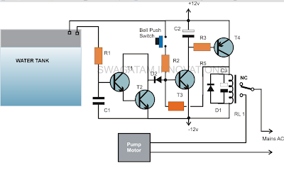
Skema Water Level Control (Semi Automatic)
Komponen :
R1 = 1K,
R2 = 470K,
R3 = 10K
R4 = 100K
T1, T2, T3 = BC547,
T4 = BC557
R2 = 470K,
R3 = 10K
R4 = 100K
T1, T2, T3 = BC547,
T4 = BC557
C1 = 0.22uF
C2 = 10uF/25V
C3 = 100uF/25V
D1,D2 = 1N4148,
Relay = 12 volts/SPDT
Push Button = Bell push type
C2 = 10uF/25V
C3 = 100uF/25V
D1,D2 = 1N4148,
Relay = 12 volts/SPDT
Push Button = Bell push type
Rangkaian yang disajikan untuk memantau level air naik di dalam tangki dan secara otomatis mematikan motor pompa setelah air mencapai level tertinggi.
Rangkaian ini sangat sederhana dan dapat dipahami dengan uraian sebagai berikut :Rangkaian ini terdiri dari transistor dan beberapa komponen pasif lainnya .Transistor T3 dan T4 bersama dengan bagian-bagian yang terkait membentuk sirkuit latch sederhana .Ketika push button ditekan sesaat , T2 mendapat bias maju dan memberikan yang diperlukan biasing untuk T4 yang juga langsung bekerja.Ketika melakukan T4 , yang mengaktifkan relay dan motor pompa diaktifkan ON .Sebuah umpan balik tegangan dari kolektor T4 mencapai dasar T3 melalui R4 memastikan bahwa T3 tetap terkunci dan dalam modus melakukan bahkan setelah tombol dilepaskan .Setelah air mencapai tingkat ambang tangki terjadi kontak dengan sepasang terminal diposisikan pada ketinggian yang diinginkan di dalam tangki .Air menghubungkan dua terminal dan tegangan kebocoran mulai mengalir melalui mereka yang menjadi cukup untuk memicu pasangan Darlington terdiri dari T1 dan T2 T1/T2 melakukan dan segera alasan sinyal umpan balik pada dasar T3 .T3 dihambat dari biasi tegangan dan latch sehingga relay OFF.Rangkaian tetap dalam posisi ini sampai air di dalam tangki masuk di bawah terminal dan tombol push di ON lagi.
Over Head Tank Water Level Indicator cum Controller Circuit
The circuit provided in this article performs a dual function of both,
as an over head tank water level indicator as well as a controller. The
indications of the rising water are provided by five LEDs, which light
up sequentially in response to the rising water level inside the tank.

As soon as the water reaches the uppermost level of the tank, the last sensor positioned at the relevant point triggers a relay which in turn switches the pump motor for initiating the required water evacuating action.
The circuit is as simple as it could be. Use of just one IC makes the entire configuration very easy to build, install and maintain.
The fact that impure water which happens to be the tap water that we receive in our homes offers a relatively low resistance to electricity has been effectively exploited for implementing the intended purpose.
Here a single CMOS IC 4049 has been employed for the necessary sensing and executing the control function.
Another interesting associated fact that’s associated with CMOS ICs has helped in making the present concept very easy to implement.
It is the high input resistance and sensitivity of the CMOS gates which actually makes the functioning completely straightforward and hassle free.
As shown in the figure, we see that the six NOT gates inside the IC 4049 are arranged in line with their inputs directly introduced inside the tank for the required sensing of the water levels.
The ground or the negative terminal of the power supply is introduced right at the bottom of the tank, so that it becomes the first terminal to come in contact with water inside the tank.
It also means that the preceding sensors placed inside the tank, or rather the inputs of the NOT gates sequentially come in contact or bridges themselves with the negative potential as the water gradually rises inside the tank.
We know that NOT gates are simple potential or logic inverters, meaning their output produces exactly the opposite potential to the one that’s applied to their input.
Here it means as the negative potential from the water bottom comes in contact with the inputs of the NOT gates through the resistance offered by the water, the output of those relevant NOT gates sequentially start producing opposite response, that is their outputs start becoming logic high or become at the positive potential.
This action immediately lights up the LEDs at the outputs of the relevant gates, indicating the proportionate levels of the water inside the tank.
Another point that’s to be noted is, all the inputs of the gates are clamped to the positive supply through a high value resistance.
This is important so that the gates inputs are initially fixed at the high logic level and subsequently their outputs generate a logic low level keeping all the LEDs switched off when there’s no water present inside the tank.
The last gate which is responsible for initiating the motor pump has its input positioned right at the brim of the tank.
It means when the water reaches t the top of the tank and bridges the negative supply to this input, the gate output becomes positive and riggers the transistor T1, which in turn switches the power to the motor pump through the wired relay contacts.
The motor pump stats and begin evacuating or releasing the water from the tank to some other destination.
This helps the water tank from overfilling and spilling, the other relevant LEDs which monitors the level of the water as it climbs also provides important indication and information regarding the instantaneous levels of the rising water inside the tank.
Parts List
R1 to R6 = 2M2,
R7 to R12 = 1K,
All LEDs = Red 5mm,
D1 = 1N4148,
Relay = 12 V, SPDT,
T1 = BC547B
N1 to N5 = IC 4049
All the sensor points are ordinary brass screw terminals fitted over a plastic stick at the required measured distance apart and connected to the circuit through flexible conducting insulated wires (14/36)
Source : http://homemadecircuitsandschematics.blogspot.in
Subscribe to:
Posts (Atom)